• Search
  • Email
Superior Product Quality

Experience the best in SWI products.

Flexible Partnership

Adapting to your needs at every stage.

Industry Leadership

40+ years in the EWI industry

  • Search
  • Email
Superior Product Quality

Experience the best in SWI products.

Flexible Partnership

Adapting to your needs at every stage.

Industry Leadership

40+ years in the EWI industry

Roofline Closure Systems

Roofline closure systems are now approved for PAS projects, allowing the use of metal flashings to protect EWI systems instead of extending rooflines.

Roofline requirements vary significantly within a scheme or property, requiring multiple solutions. Since standard details cannot cover all scenarios, a set of Design Principles has been established. These principles provide flexibility while ensuring robust and durable details for long-term protection of EWI systems.

Below are the steps to help you understand the new guidance and the installation requirements going forward.

1. Design Principles

Roofline closure system solutions are designed according to a set of core Design Principles. This approach ensures that designs can be adapted to accommodate the diverse rooflines and features of different properties, as long as all principles are adhered to. For more information, see below.


Explore The Design Principles

  • 1. Redundancy of Seals
  • 2. Gable-to-Eaves Junctions
  • 3. Gable Apexes Formation
  • 4. Jointing Pieces/Connectors
  • 5. Soffit/Roof Overhangs
  • 6. Thermal Bridging
  • 7. Lead Flashings
    • Utilise at least two layers of weather protection.
    • Avoid relying solely on sealants for waterproofing.
    • Consider additional redundancy with trim or membrane.
    • Double-seal all joints.
    • Provide secondary waterproofing at eaves.
    • Ensure appropriate system overhang per exposure zone.
    • Use overlapping, prefabricated units.
    • Prohibit site fabrication except for minor trimming.
    • Stagger joints by 100 mm.
    • Use prefabricated elements.
    • Use site bent flashing with secondary lead flashing if necessary.
    • Prohibit site-formed mitre joints.
    • Use connectors with extended sides.
    • Seal connectors to metal profiles.
    • Stagger joints by 100 mm.
    • Embed flashings/trims into masonry or below cement pointing.
    • Overlap joints between redundancy layers by 100 mm.
    • Replace sand and cement fillet with flexible mortar.
    • Ensure insulation continuity for minimum thermal resistance.
    • Limit single-piece lead length to 1200 mm.
    • Follow best practice for overlaps and installation of lead or lead replacement flashings.

* Roofline Closure details that do not meet the requirements above are not acceptable for use with any funded or Private schemes requiring a third party warranty

2. Survey Suitability

To ensure the successful installation of Roofline Closure Systems, a thorough property survey is essential. This assessment helps determine the suitability of the systems and identifies all necessary details. Early identification of these details is crucial, as multiple specifics may be required.

Accurate measurement and recording of the existing roof overhang are vital since they dictate the needed specifications. Additionally, evaluating the condition of the substrate is important to confirm the property can support the installation, particularly for grind-in flashings.


Explore the Assessment Criteria

PRIMARILY THE SURVEY MUST ASSESS THE FOLLOWING;

  • 1. Relevant Details
  • 2. Existing Overhang
  • 3. Rafter Positioning
  • 4. Substrate Condition
  • 5. Existing Insulation & Potential Cold Bridging
  • 6. Corner Details
  • 7. Existing Features
  • 8. Ventilation
  • What will work with the existing roof line/ substrate.
  • Ensuring it is consistent across the eaves/ verge.
  • Rafters may need to be boxed in, worked around or altered.
  • Where grinding in is to be considered, ensure the substrate is stable and will not be damaged by grinding in.
  • From installing each detail, ensuring continuity of roof insulation and a minimum thermal resistance of 0.6m²K/W.
  • Confirming how the eaves and verge will meet and what the best detail is (where required, which corner profile is suitable).
  • Such as corbels and quoins will need to be considered and may prevent these details from being installed, resulting in site specific designs being undertaken in line with the Roofline Closure principles.
  • Roof ventilation must not be obstructed/ restricted when installing Roofline Closure Systems.

* Some properties create roof junctions that are extremely difficult to find a solution for, and therefore extending the properties roofline may be the best option.

A Survey Form must be completed to record the survey findings, substrate condition, existing overhangs, etc. The survey form must be submitted to apply for a project warranty.

REQUEST THE SURVEY FORM

3. Second Line of Protection

Explore the Options The Roofline Closure System Principles require 2 layers of protection across the top of the EWI system. This can be achieved in several ways; Wetherby offers 2 standard solutions. Selecting the preferred solution for installation will dictate the specific Wetherby details required.

FOR FURTHER INFORMATION ON SECONDARY FLASHING DETAILS PLEASE CONTACT WETHERBY TECHNICAL DEPARTMENT email the team at Technical@wall-systems.co.uk 0r call us on 0800 107 32 99

Membrane Vs Secondary Flashing

Pg 9 roofline closure system guide


  • Installing a membrane below the primary flashing can be a cost-effective solution.
  • Membranes can be adhesively fixed to the substrate / EWI or clipped to the primary flashing.
  • Membranes must be suitably water tight to ensure protection for the system.
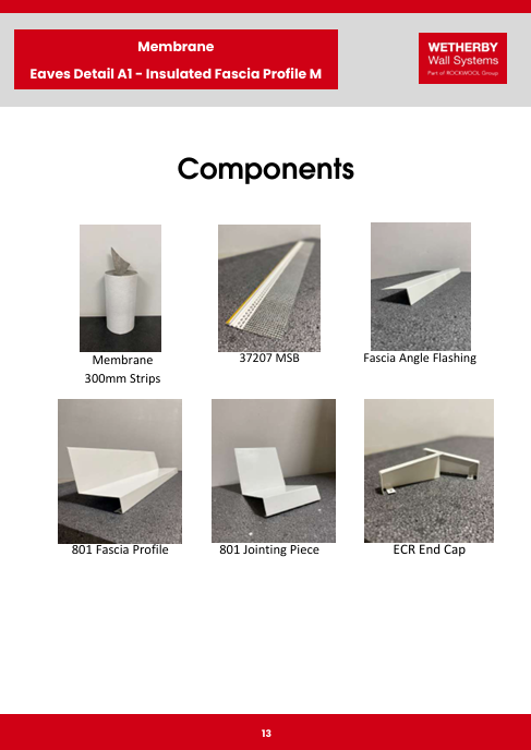
  • Wetherby supply a specialised membrane stop bead (MSB) to be used at the top of the insulation board, providing an adhesive tape to fix the front of the membrane to.
  • Wetherby membranes are supplied in 300mm width roles to simplify installation.
  • Membranes must be overlapped by min 100mm and taped in line with the manufacturers guidance.

4. Guide Information

Wetherby Roofline Closure System Guide

The Wetherby Roofline Closure Systems Guide provides practical guidance for selecting PAS-compliant roofline closure details for EWI systems.

The right detail will depend on the existing roofline, overhang, exposure zone, substrate condition, ventilation and potential cold bridging.

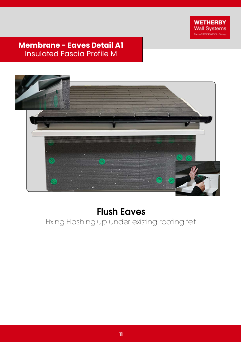
Page 10 of the guide provides a clear detail list to help designers and installers identify the most suitable eaves or verge option before work begins. For complex details, please contact the Wetherby Wall Systems Technical Department.


Membrane - Roofline Closure System

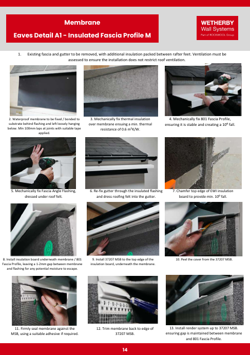
The guide provides 4 pages of specific install information for each detail which includes:

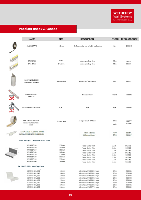
Including a detailed index, listing all components, product sizes / lengths / dimensions and Wetherby product codes to assist in ordering materials:

5. Application Demo Videos

Here you’ll find a series of demonstration videos that reveal the intricacies of Roofline Closure Systems.

Eaves Detail A1

Eaves Detail A2

Verge Detail A3

Verge Detail A4

6. Installation Checklist

During installation, a checklist form must be completed to provide information on how the Roofline Closure System principles are being met on an installation. Photographic evidence of the various installation steps is also required; this information must be submitted to apply for a project warranty.

REQUEST THE CHECKLIST

7. Minimum Material Specification

The Roofline Closure System principles include a minimum specification for the flashings to which Wetherby components are manufactured:


Minimum Material Specification

  • 1. Suitable Base Material
  • 2. Minimum Thickness
  • 3. Coating Requirement
    • Minimum Aluminium specifications 1050A. Minimum Stainless-Steel specifications 304.
    • 1.2 mm aluminium with a tolerance of +/- 10% to be used for trim widths up to 160 mm.
      For trim widths over 160 mm or trims to be used in exposed areas, (minimum 50 mm overhang) 1.5 mm aluminium must be considered for added strength and stability.
    • Polyester Powder coated aluminium must have a minimum coating thickness of 40 microns to BS or Qualicoat standards and Powder Coaters must be BS or Qualicoat-approved applicators. Pre-coated aluminium must be polyester coated on both sides and the thickness must conform to EN 13523-1.

8. Ancillary Items

There are a number of ancillary items required when installing Roofline Closure systems which are described and listed below with more information in the Wetherby Guide.


Ancillary Items

Including;

  • Jointing Pieces
  • Gable Apexes
  • End Caps
  • Gable to Eaves Junction
  • Downpipe Boxes
  • must extend 40mm on each side of a joint
  • Prefabricated profiles must be used
  • Required on all primary flashings
  • Prefabricated corner profiles required
  • Required at swan neck junctions

Contact the Team at Wetherby Wall Systems

We understand that embarking on a construction project is a significant endeavor, and we’re here to support you every step of the way.

If you have any inquiries, require additional information, or would like to discuss your specific project needs, please don’t hesitate to reach out. Our dedicated team of experts is ready to listen, collaborate, and provide tailored solutions.

Contact Us

    I would like to receive news and updates from Wetherby Wall Systems Ltd.

    We will only contact you in relation to latest news and updates that we think will be of interest to you. We will not disclose your information to any third party and you can unsubscribe from our database at any time.

      Please fill out the form below, your download will automatically start. Your download will also be available via email in case it doesn't automatically start.


      Stay up to date with Wetherby Wall Systems. From time to time, we’d like to send you relevant technical updates, product information, CPD opportunities, specification guidance, events and industry insights.